Promise this is the last tech article for a while. I just need to get these caught up. We have been busy so I have lots to catch up from since Vero!
This all started with the purchase of a RaspberryPi and I installed Signal-K. I added Whilhelm SK (https://www.wilhelmsk.com/) to an available Apple Ipad and said “this is cool.” I do not have easy access to display data from my solar panel output so the next step was a no brainier. If I could get current and voltage data onto the Whilhelm SK display, now that would be REALLY COOL.
Goals
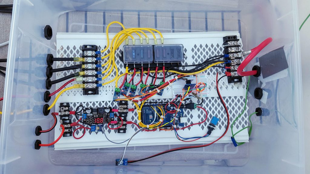
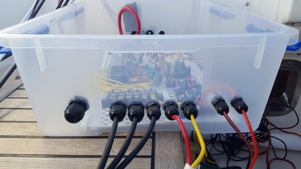
1) The collection electronics would be contained in a weather “resistant” container located in the fly-bridge area.
2) Data collection system must have a wireless connection to the Raspberry Pi (RPi) and the Signal K Server (After last years overhaul, I am done pulling cable)
3) Must provide current collection for each of the 6 solar “banks” we have installed.
4) Temperature and humidity data inside the weather “resistant” container must be reported. (Make sure we don’t have moisture intrusion)
5) Voltage of the power source powering the data collection system must be reported. (This happens to be my dinghy hoist battery which is charged by a separate solar panel.)
I quickly decided the collection system would be centered around an Arduino Mega board. After some research the following shopping list was made. All the following components were ordered from Amazon.
A) 24V to 12V 5V DC Converter, DROK LM2596 Buck Power Converter 5-32V to 0-30V Step Down Adjustable Output Voltage Regulator Board Power Supply Module with LED Display Voltmeter Screw & Heatsink — $15.83 –
B) SunFounder Mega 2560 R3 ATmega2560-16AU Board Compatible with Arduino – $14.99
C) 20A range Current Sensor ACS712 Module – $4.60 each (one for each monitored panel/bank is required)
D) WINGONEER 5PCS Max 25V Voltage Detector Range 3 Terminal Sensor Module for Arduino – $6.99 for 5 (Only two are required in this implentation – 5 was just the number in this offer)
E) Gowoops 2 PCS DHT22 Temperature Humidity Sensor Module Digital Measurement for Arduino Raspberry Pi 2 3 — $9.99 (Only one is required in this implentation – 2 was just the number in this offer)
F) Aideepen ESP8266 Serial Wi-Fi Wireless ESP-01 Adapter Module 3.3V 5V Compatible for Arduino – $6.99 –
G) HiLetgo FT232RL FTDI Mini USB to TTL Serial Converter Adapter Module 3.3V 5.5V FT232R Breakout FT232RL USB to Serial Mini USB to TTL Adapter Board for Arduino — $5.99 –
H) SMAKNÂ DC 3.3V 1A Switching Power Supply Adapter 100-240 AC — $5.99
I) DIYmall ESP8266 ESP-01 with Breakout Board breadboard Adapter PCB for Serial Wifi Transceiver Network – $7.99
J) Male Barrel Plug 6-Inch Wire 5.5mm x 2.1mm for LED Strip Light, CCTV Security Camera, DVR, and Other Low Voltage Applications – Used to connect Buck-Converter to the Arduino for power. – $3.49
K) Elegoo EL-CK-002 Electronic Fun Kit Bundle with breadboard Cable Resistor, Capacitor, LED, Potentiometer (235 Items) – $12.86
The first step was to get the WIFI adapter working with the Arduino. I accomplished this task using the YouTube tutorial: “Arduino Mega 2560 with ESP8266 (ESP-01) Wifi, AT Commands and Blynk” –https://www.youtube.com/watch?v=YLKEZtLhfZo
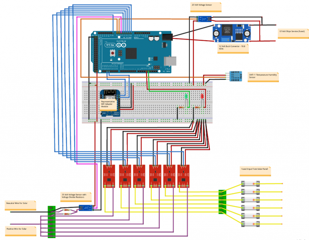
Assemble the circuit according to the diagram below. Note the buck converter is set to output 10.8 volts. See Buck Volt regulator is Handy Gadget for under $10, Step Down LED Driver product review: (https://www.youtube.com/watch?v=l7DVyas-lkw).
The wire connection list is as follows:
1) Buck Converter Input – requires a fused (10amp) 12volt input – DO NOT forget the fuse! The Buck Converter provides a regulated voltage to the Arduino and sensors. Output is set to 10.8 to ensure sufficient voltage is available for sensors.
2) Mega 2560 Input – Connect the output from the Buck Converter to the appropriate connetions on the Male Barrel Plug, and plug into the Mega 2560
3a) Mega 2560 Output – Connect the negative pin (pin closest to Pin 52) to the negative bus of a Breadboard
3b) Mega 2560 Output – Connect the positive 5v pin (pin closest to Pin 22) to the positive bus of the Breadboard
3c) Breadboard – DHT11 sensor into the breadboard as shown.Connect the negative and positive pins to the negative and positive bus. Connect the data pin to the Mega 2560 Pin A8.
3d) Breadboard – Insert ESP8266 ESP-01 with Breakout Board Breadboard Adapter with the mounted ESP8266 Serial Wi-Fi Wireless ESP-01 Adapter Module. Connect the negative and positive pins to the negative and positive bus.
– Connect the Mega 2560 Serial Tx1 Pin 18 to the Rx Pin on the Breakout Board Breadboard Adapter
– Connect the Mega 2560 Serial Rx1 Pin 19 to the Tx Pin on the Breakout Board Breadboard Adapter
Note: The Transmit and Receive pins need to be connected to their opposites (Tx-Rx and Rx-Tx) between the Mega and ESP8266
3e) PCB Board – Insert a Red and Green Led into the PCB along with a 220 ohm resistor in serial. Connect the positive side of the Red LED to PWM Pin 12 and the Green LED to PWM Pin 13.
3f) There are two voltage sensors. The Solar Array (panel) voltage sensor us used to measure the voltage output by the solar panels. To determine the actual energy (power=watts) being produced by the array requires both the voltage(V) x Current (I) = Watts (W).
The second voltage sensor measures the supply voltage being provided to the Buck Converter input. I use a battery and seperate small wattage solar panel to power the sensor board.
3g) Connecting the solar panels is pretty straight forward. First thing all the solar panel negatives are connected together and tied to the negative connection to the charge controller. I used a standard block for this. The individual solar panel positive connections are then connected to the input side terminal blocks before installing the individual fuses. (Size fuse to size of solar panel/bank)
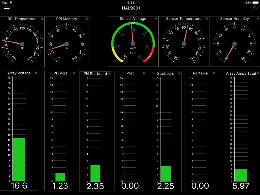
I used the WhilhelmSK to build the below display screen for the solar panel application. As you can see right off the bat I uncovered a couple of issues with my system which I will be going to investigate!
The setup is not perfect. I am still working to improve the accuracy of the current sensors. I have not decided exactly what I am going to do. There is an opprotunity to solder an additional capacitor but not sure my skills are that could. There is certainly more tweaking in software to do.
Speaking of software, the code and this document will be available on GitHub.
https://github.com/awwbaker/Solar-Sensor-Board