This document assumes this is not your first Arduino implementation. If so please contact me for specific implementation help
This is a home-built sensor is the latest addition aboard Magnolia. The purpose is to collect the primary bilge pump run frequency and run duration. Magnolia has a traditional stuffing box and the bilge is MOT dry. Our bilge pumps have always popped on as required, but I never had any understanding of how long and how often. We now have that data.
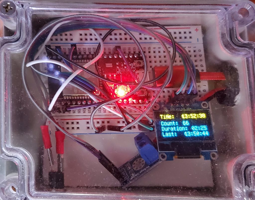
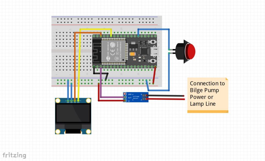
Hardware: The sensor itself is very simple. There is an ESP-32S Processor Board , 25V Voltage Detector, 1.3″ IIC I2C Serial 128×64 SSH1106 OLED LCD Display LCD Module along with a Breadboard and connecting jumper wires. There is also a small push button to enable downloading of new software to the ESP-32. All items are readily available on Amazon.
The below Fritzing file is availble at: https://drive.google.com/open?id=16hcxkLP8NNJhmCP00F-pebd04jTqR8gh
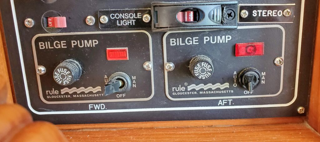
I used some Piggy Back Spade Quick Splice Crimp Terminals Connectors to attach the sensor to the back input of my Bilge Pump Control Panel ensuring the sensor was receiving power whenever the bilge pump light illuminated.
Software: Three of the sensors on Magnolia use the same codebase and applicable sections are controlled pre-processor directives. The specific Bilge Sensor code is available at: https://drive.google.com/open?id=1qqcYzlBnlc_VfFYIYtKl8uIyEPSApwfq
The following paths are reported to the Signal-K Server:
| environment.inside.bilge.currenttime | “19:32:28” | |||
| environment.inside.bilge.lastruntime | “19:30:44” | |||
| environment.inside.bilge.runcount | 110 | |||
| environment.inside.bilge.runduration | “04:02” | |||
| environment.inside.bilge.rundurationmils | 242 | |||
| environment.inside.bilge.status | “Stopped “ |