If you think this “Part #2” was a long time in coming you should be on this end!!! Truthfully a big project but on the other hand, I have not been killing myself either! The great motivator as always, the calendar! With less than a month to go before we start the fall migration it was time to finish this job up! Back to the beginning first though.
Essentially the water maker is made up of the following components. (TL clockwise). Control Panel, Boost Pump, Charcoal Filter, HP Pump, Membranes and Raw Water Filter. A VERY quick water maker theory class, the boost pump receives raw seawater and pressurizes to about 30psi. The seawater is sent through the 20 and 5 micron filters before being fed to the HP Pump which pushes the seawater into the membranes at 850psi. The output of the Membranes is a salt-free drinkable water at about 30 gallons per hour.

The first exercise was to locate a place on Magnolia where to install the equipment? The ideal location would be: 1) Near an existing thru-hull to receive the raw saltwater. 2) Near the fresh water tank. 3) Location where the filters are easily accessible. 4) A location with good drainage to the bilge for inevitable spillage when changing filters. 5) Accessibility to a A/C 20amp breaker. In the case of Magnolia I think we scored exceptionally well with perhaps accessibility to the the filters for easy changing. I will let you know in the spring after we live with the system for a season.
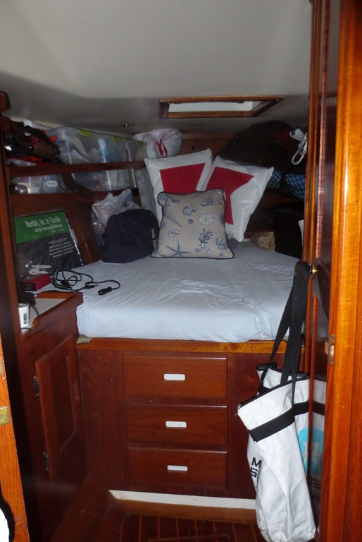
In the case of our Morgan 44 the ideal location is under the forward berth. The water tank is under the berth (18 inches away, there is a thru-hull directly aft of the berth and the location is directly over the forward bilge.
The location currently contains 3 VERY shallow drawers. To make the space accessible we need to remove the drawers and replace them with cabinet doors. We stopped at every consignment shop along the east coast on our way north last spring. The “Lucky Duck” finally scored in Hampton VA at a cost of $10.00 a piece and they match just about perfect!
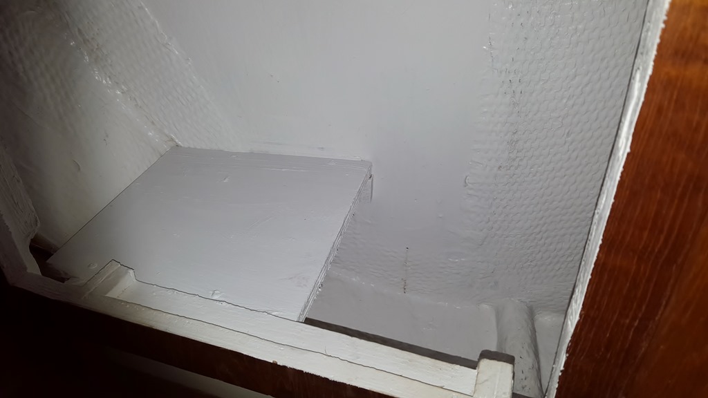
The first action was to install a shelf on which to mount the High Pressure Pump
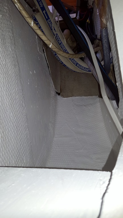
I took the opportunity to fully replace the sanitation hoses for the forward head which made the job significantly larger than initially planned. (That is ALWAYS the case on a boat so no real surprise there)
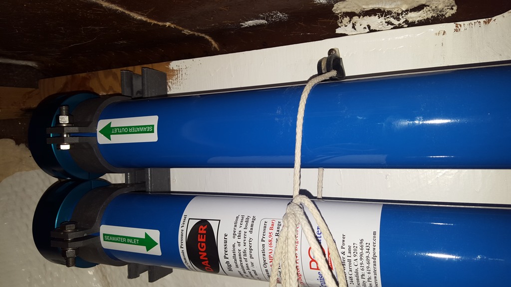
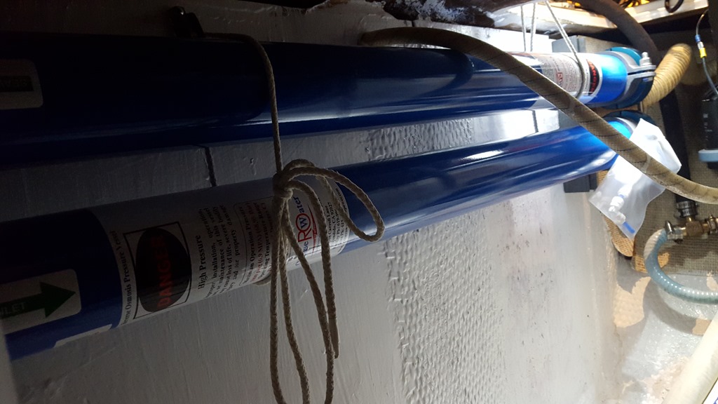
It was then just an exercise to install largest components first. Note: The string is only used during installation. Its not permanent.
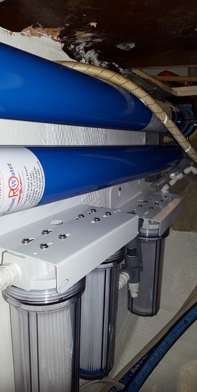
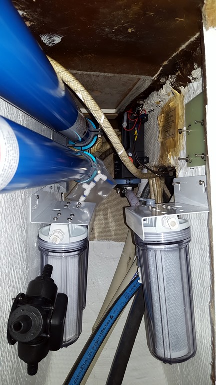
I did tons of measuring and thinking before the installation began but it was not until a component was installed that I was able to determine if that was the best choice. To illustrate you might notice the filters were re-positioned in the below pictures. A subsequently the black 3-way valve was also relocated.
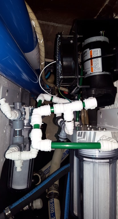
Eventually the configuration ended as seen below.
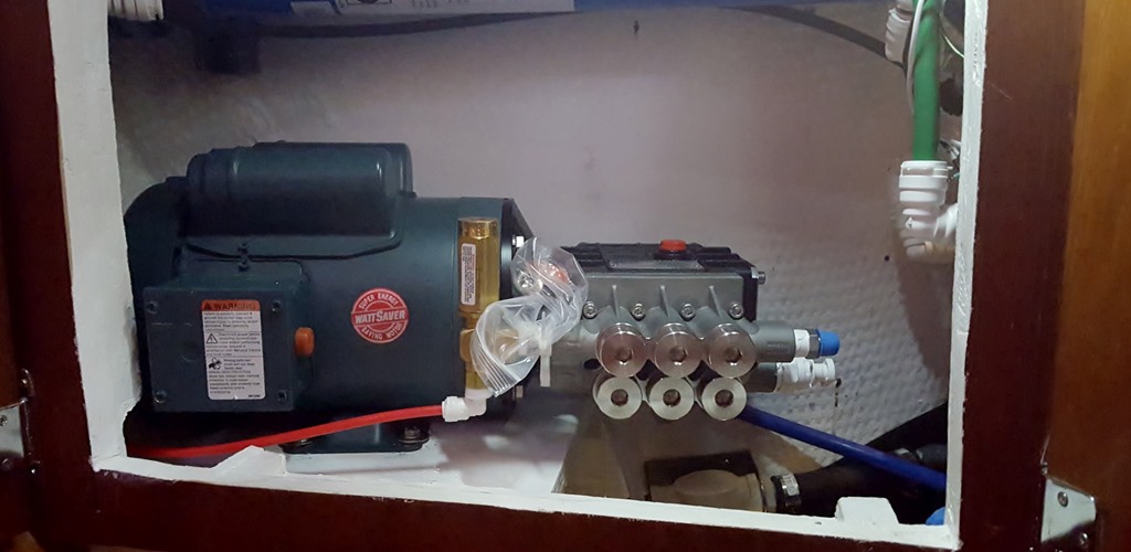
The final component is the 48lb high pressure pump.
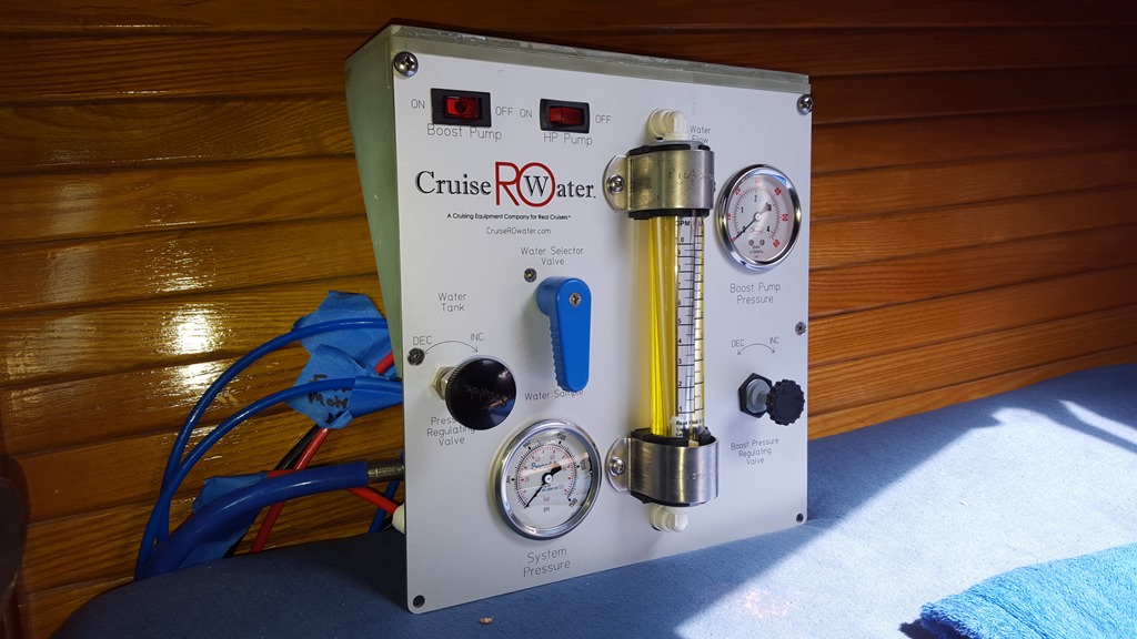
The control panel has all of the lines connected and ready to go. The mounting has been dry fit and should work out nicely.
The system uses Magnolia’s 120volt service which is similar to how a house is wired but since this “house” sits in water I am having a professional come in and make the final electrical connections. Hopefully that will be done this week. We will keep you apprised!


Wow, doing a great job. You must be a good contortionist by now.
I agree with the contortionist comment. Lots of twisty, turny things going on there!
Just finished my install 6 weeks ago. Rich and Charlie at RO Cruise water were great to deal with. I have the 30 gph unit also. Our boat is a beneteau 473 and we are heading south this winter.
Will be this your first season? I hauled water for the first two seasons figured for #3 I would splurge and in addition I think we will be more inclined to wander a bit further a-field.
I just installed the same unit. Lessons I learned after initial start up we re that I used too many joins and elbows. I see several in your installation that could be removed and replaced by a section of hose long enough to reach to major components and bent to take the corners by heating the hose with a hair dryer. I was able to achieve 90 degree turns with no problem and in one case I did a 180 degree turn to the pressure pump in a space under 14 inches wide. By eliminating joints you eliminate leaks. 2nd thing I learned is that I thought I had joined the fittings to the hoses tightly but after leaks I learned that I had not seated many of them far enough. Seat them hard. Lastly the run line from my water tank back to the cleaning assembly was too long as I tried to tie into a boat non pressures line. I could not sustain the water flow for the wash down and shortened the run by connecting to a pressure line nearer the cleaning assembly. That eliminated the lift pressure problem I had and I now achieve the required 10PSI with the boat water pressure pump and leaving the RO system lift pump off for the back wash procedure. One more thing. Make sure you follow the shut down procedure fully including the back wash clearance of the system every time you make water. I followed advice of people who said unnecessary if you make water again in 3days. Not so, I ended up with the rotten egg smell and had to follow the pickling procedure to resrerilize the system. Looking at your photos again, make sure you can easily get to the three way switch on the cleaning assembly, you will be using that switch all the time. Hope this is helpful. Would have saved me a lot of time had iknown these things up front. JM
John appreciate you taking time to share your thoughts. At this point though I am just gonna see where the leaks pop out. I made sure all the lines were FIRMLY seated in the fittings so we will see how I did!